Telephone REN Extender
(C) 2002 Ralph Bolton
Purpose
This circuit increases the amount of current available on a telephone line for ringing phones. Typically, the REN (Ringer Equivalence Number) for a domestic telephone line is around 4. Since most telephones are REN1, this means that a maximum of four phones can be used on a line. With this circuit, the REN becomes much higher, potentially unlimited. This is useful where more than four phones are to be used, or where a long cable run is required (for example, putting a phone in an out building, perhaps a shed or garage).
Very BIG Disclaimer
This circuit is totally illegal. It is illegal to attach anything that is not specifically approved to a telephone line. Serious penalties are possible. Similarly, any minor mistakes in building (or indeed in the design) could result in (expensive) damage to a telephone exchange, which would be a very bad thing for you, your bank balance and possibly your criminal record. I believe this circuit works - you may have different views or experiences to me, and I take no responsibility for anything that happens if you use this information.
You do anything with the knowledge on this page entirely at your own risk.
Circuit Diagram
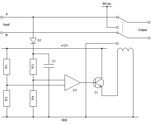
<img src=" " alt="Telephone REN Extender Circuit Diagram" title="Telephone REN Extender Circuit Diagram"class="image image-img_assist_custom-640x526 " width="530" height="436" />Telephone REN Extender Circuit Diagram
Parts List
R1 100M, 0.25W
R2 100M, 0.25W
R3 100M, 0.25W
R4 100M, 0.25W
D1 1N4001
D2 12V Zener diode
C1 1uF
IC1 741
T1 BC108
Switch dual DPST, 12V coil (mercury wetted if possible)
Description
The circuit switches 50Vac onto the output lines when the input lines ring. This is designed to be both a reasonable simulation of a real telephone exchange, and also easy to construct (see PSU details below). While ringing, the exchange (the input) is switched out, leaving any upstream phones or equipment independent of those downstream.
To detect ringing, the high voltage of the ring is compared with a fixed 6V (created by R1 and R2). The 741 is used purely as a comparator, it's output going to 12V when ringing takes place, which makes T1 conductive, energising the coil, making the electromagnetic switch connect the 50Vac supply to the output.
Since the input ring voltage could be huge (50-100Vac is normal), the voltage is dropped considerably by R3 and R4. The comparator's input is protected by a 12V zener diode, D2. This ensures the comparator never has an input greater than 12V. C1 provides "smoothing" to the half-wave rectified input signal. This smoothing effectively makes the input a DC level, meaning the coil is energised constantly for the duration of the ring.
When the input line is either in use or "on hook" then the circuit presents very little to the line. The R1/R2 connection presents a very high impedance, similarly to the D1/R3/R4 connection. Since the output is connected almost directly to the input while not ringing, downstream equipment is unaffected. Power supply failures also leave the circuit in a "fail safe" mode. Of course, at such times, telephone ringing may be impaired.
Power Supply
This description is based on 240Vac mains supplies.
Circuit Diagram
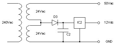
<img src=" " alt="Telephone REN Extender Power Supply" title="Telephone REN Extender Power Supply"class="image image-_original " width="388" height="151" />Telephone REN Extender Power Supply
Parts List
D3 1N4001
C2 100uF
IC1 12V Power Supply IC
Transformer dual 24V isolated
Description
The circuit uses a 50Vac and 12Vdc supply. This absolutely must be isolated from the mains supply.
In this circuit, D3 and C2 half wave rectify and poorly smooth a 24Vac supply. The intention here is that the smoothed supply wave never drops below around 15V, thus providing enough voltage for IC2 to properly supply a 12V output. As a result, D3 and C2 are deliberately inefficient, such that they do not provide a high mean voltage (highly efficient rectification and smoothing would result in around a 30V supply). Excess voltage at this point has to be dropped by IC2, which causes it to heat up considerably. Keeping the input voltage and output current low means that the IC should operate reasonably without a heat sink (although using one may be beneficial).
It may be advisable to AC isolate IC2's input and output with a 1uF capacitor, mounted as close to the pins of IC2 as possible. C2's size may need adjusting, depending on the current drawn by the main circuit during ringing. The outputs of this power supply are isolated from the mains, and as such are reasonably safe, and can be connected to the REN Extender.
---
This circuit was originally devised in 1991-1992 by Ralph Bolton, and is an original work.